CCTV DVR Alarm Input Recording
This video demonstrates the alarm input recording setup for iDVR-PRO CCTV / AHD hybrid DVRs. Please note that CCTV Camera Pros now recommends Viewtron hybrid security camera DVRs. You can find those DVR alarm input setup instructions here. The DVR alarm relay output setup instructions are here.
Alarm Input / Output Terminal Block
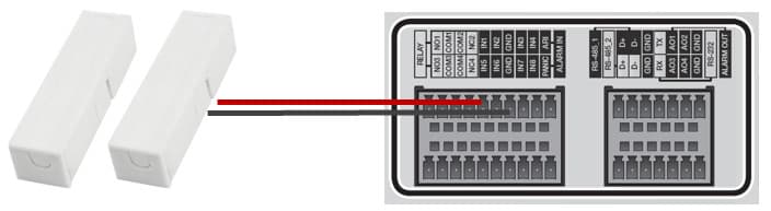
In order to setup an alarm input with your DVR, you will first need to confirm that the surveillance DVRs have an alarm input panel which is typically located at the back of the DVR. An example of an alarm input panel can be seen below. In this example we also used magnetic alarm sensors which can be used as window or door sensors.
Door and Window Sensors
The wiring required to setup a window or door sensor to a surveillance DVR is typically 18/2 power cable or 1 of the pairs from a CAT-5 network cable. One of the contacts or the door / window sensors has a terminal that the cable attaches to.
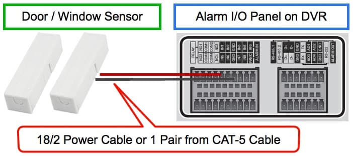
The right side of the diagram shows the alarm input block on the back of the DVR. One of the wires connects to a DVR alarm input port and the other connects to a ground terminal. These door and window sensors do not require a power supply.
The surveillance DVRs alarm must also be configured to trigger an alarm when the magnetic link is broken by a window or door opening. Notice how the ports are labelled to assist in the setup.
Motion Detector Wiring to Security Camera DVR
Wiring a motion detector to a DVR works in a similar way as a door or window sensor with the exception that the PIR motion sensors will also require power.
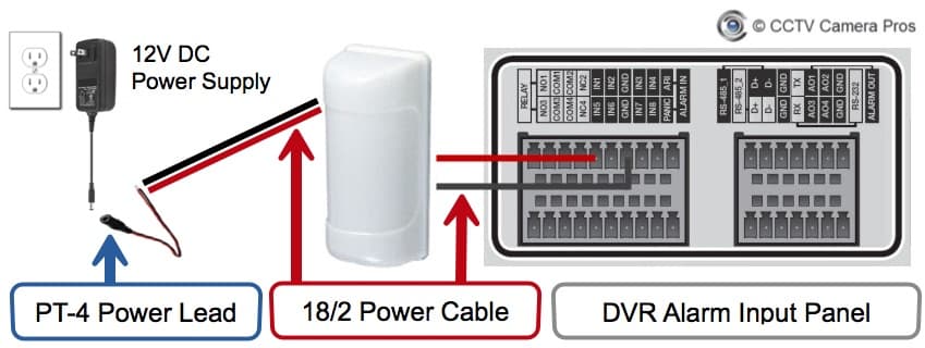
In the above diagram the motion detector is hard wired to the DVR using the same 18/2 power cable as used with window and door sensors. The motion detector will then be connected to one of the alarm input ports on the back of the DVR.
18/2 power cable is also going to be used to connect the motion detector to an individual 12V DC power supply. The power supply uses a 3.1mm plug. In order to transform the 2 raw power leads to a 3.1mm male connector a PT-4 power lead can be used.
Alarm Input Recording Options
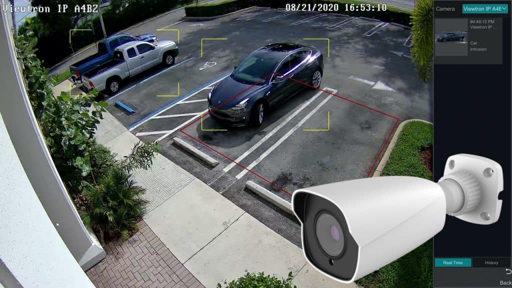
When setting up a home security or business security system, there are several recording options that are available to select from. When all of your security cameras have been mounted and positioned you may want to setup different recording options for certain cameras. iDVR-PRO DVRs allow for each camera on the system to be configured to record based on different rules. One option is to setup recording based on a trigger from an alarm inputs.
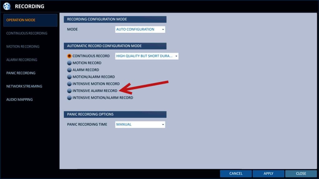
The above image shows one of the screens used to configure alarm based recording. You can see all of the alarm recording setup instructions here.
Here is a list of the all of the supported video recording modes.
- Continuous Recording- 24/7 recording.
- Scheduled Recording- records continuously according to a configured schedule.
- Motion Detection Recording – records when video motion is detected by a camera.
- Alarm – records when an external alarm triggers an alarm (such as a motion sensor).
- Motion / Alarm – records when motion is detected or when an alarm is triggered
- Intensive Motion – records continuously and when motion is detected.
- Intensive Alarm – records continuously and when an alarm is triggered.
- Intensive Motion / Alarm – records continuously and when motion is detected or an alarm is triggered.
- Panic Recording – triggered when a user presses the panic button on the DVR. It causes the DVR to record continuously on all cameras.
Setting up Email Alerts and Push notifications are also available.
You can learn more about the recording options mentioned above by clicking here.
Alarm Output
Burglar alarm sensors can also be used to trigger alarm outputs on external alarm devices such as audio sirens and strobe lights. The user can setup their DVR to sound an audio alarm or activate a security light when a door is opened or motion is detected for example. Each iDVR-PRO model has a different number of alarm outputs. For example, the 16 Channel iDVR-PRO has 16 alarm outputs ports.
The following events can be configured to trigger one or more external alarm relays.
- Alarm Sensor – if you set up external alarm inputs, they can be used to trigger alarm outputs.
- Video Motion Detection – video motion detection from any camera.
- Video Loss – video being lost on any camera from loss of power or tampering.
- Disk Drive Alert – disk drive system events such as disk full, failure, overwrite started.
- Network Event – network events such as remote login failure, Internet connection failure, and DDNS update failure.
- Panic Recording – initiation of panic recording.
- System Event – system boot-up warning, login failure, fan failure.
- Tamper Detection – DVR tampering detected.
DVR Alarm Relay Output Wiring
The usage for alarm relay output ports and the digital alarm outputs is different. When using relay outputs, the power source of the output device is connected in line with the relay terminals and the relay is set to be normally open or normally closed. When an alarm is triggered, the relay switches to the opposite state of the normal state (open or closed) and causes the connected device to either receive or lose power.
WARNING: DVR relay alarm outputs have a maximum power rating. The alarm outputs of iDVR-PRO have a maximum power rating of 2A 120VAC, 2A 24VDC. This rating should accommodate almost all standard low voltage burglar alarm equipment, but you should check the specification of each device to be sure. If you are using these instructions as a guide for a DVR brand other than iDVR-PRO from CCTV Camera Pros, please check the specification for your DVR!
The digital alarm output ports, on the other hand, simply send a low voltage pulse signal to the device that is connected to them. The output device must be configured to take some sort of action when the signal is received.
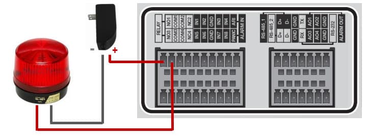
For these instructions, we are going to use one of the relay output ports and connect a 12V DC powered siren / strobe light.
The above wiring diagram shows how to wire the power supply and strobe light to the alarm relay output port #1 of the DVR. We will set the relay to normally open (NO) so that the strobe light is not powered / turned off by default.
The positive wire from the power supply connects to the NO1 port on the back of the DVR. The negative power supply wire connects to the negative power input of the strobe light. The positive wire from the strobe light connects to the COM1 port on the back of the DVR.
Last, connect the power supply to a power source.
Related Security Articles and Videos
- Surveillance System Installation Videos
- Trigger Video Surveillance Recording on a DVR
- Outdoor PIR Motion Detection Recording
- iDVR-PRO Alarm Status Indication
- Detailed CCTV DVR Alarm Input Setup